Speaking the Grid's Language: DNP3 on the Wire
Putting the simulated grid on the wire with OpenPLC as a DNP3 outstation and a scripted Python master — bridging Modbus to DNP3 inside the PLC, sending a Control Relay Output Block to open a breaker, and reading the command off the wire in Wireshark to show there is nothing in it that says who sent it.
The simulated grid from the last post works, but it only speaks Python. Real grid equipment doesn’t. It speaks DNP3, a decades-old industrial protocol for asking a substation “what are your readings?” and telling it “open that breaker.”
That’s not just a trivia detail, it’s the whole security problem. When attackers took down part of the Ukrainian grid in December 2015 and left about a quarter of a million people without power in winter, they didn’t use some exploit against the breakers. They logged into the control system and sent the commands, using the same protocol and the same format the operators used every day. The protocol itself is the attack surface, because it was designed back when just being on the network meant you were trusted.
So this post puts the simulation on the wire. I use OpenPLC, free software that emulates the industrial controller sitting in a substation, to serve the grid’s readings over DNP3. Then I write a master that polls it the way a control room would, and send the command I actually care about: the one that opens a breaker. After that I open the packet capture and show that the command contains nothing that says who sent it.
Where this fits. Post 3 of the series. Get the DNP3 loop working end-to-end and stable before you even think about layering in IEC 61850 — doing both at once is a debugging nightmare.
What is DNP3?
DNP3 (Distributed Network Protocol 3) is the workhorse SCADA protocol for the North American electric sector. In its vocabulary:
- The master is the control-center side — the software that polls for data and issues commands. Think of it as the client.
- The outstation is the equipment out in the field that reports its measurements and carries out the commands. Think of it as the server. In the real world it’s a box bolted to a rack in a substation — an RTU (Remote Terminal Unit) or an IED (Intelligent Electronic Device), which despite the ominous name is just industry shorthand for a smart field device like a protective relay. In my lab, OpenPLC plays this role, backed by the pandapower grid.
- Measurements are points, and there are only a few kinds: analog inputs (a voltage, a megawatt reading), binary inputs (a breaker is open, or closed), and the one that does the damage — the Control Relay Output Block (CROB), which is DNP3’s way of saying “operate that piece of equipment.” A CROB is what opens a breaker.
DNP3 over TCP runs on port 20000 by default. That port, where it crosses the Electronic Security Perimeter (the boundary I draw around the OT network in post 4), is basically what the whole CIP assessment exists to govern.
Here’s the important part: DNP3 has no authentication by default. No password, no signature. If you can reach port 20000, you can command the equipment. There is a secure variant (DNP3-SA), but it’s not widely deployed. That one fact is why the grid leans so hard on network segmentation and monitoring. The controls in the rest of this series exist because the protocol itself won’t protect you.
I’ll prove that later in this post with a hex dump instead of just asserting it.
Why I grounded this in a real protocol
It would be easy to skip protocols and just call a Python function to toggle a breaker. But then there’s nothing on the wire: nothing to segment, nothing to monitor, nothing to attack the way a real attacker would. Using real DNP3 is what makes every later control mean something. CIP-005 governs this port crossing the ESP, CIP-015 monitors this east-west traffic, and the rogue breaker command in post 5 is an actual DNP3 CROB, not a stand-in.
The pieces
Three VMs, each with one job, all on the isolated ot-zone network:
flowchart LR
    subgraph ot["OT / process zone (inside the ESP)"]
        grid["ot-grid — 10.10.20.10<br/>pandapower + Modbus server<br/>(grid physics, post 2)"]
        plc["ot-plc — 10.10.20.11<br/>OpenPLC<br/>Modbus master + DNP3 outstation"]
        scada["ot-scada — 10.10.20.12<br/>scada_master.py<br/>(DNP3 master / control room)"]
        grid -->|"Modbus TCP 502<br/>line loadings"| plc
        plc -->|"Modbus coils<br/>breaker commands"| grid
        plc -->|"DNP3 TCP 20000<br/>analog inputs"| scada
        scada -->|"DNP3 CROB<br/>open/close breaker"| plc
    end
That middle box is doing more than it looks. OpenPLC isn’t a protocol converter you just configure; it’s a PLC, so the conversion is a program that runs on every scan. More on that in a second, because it’s where a nasty bug showed up.
The outstation — OpenPLC
OpenPLC acts as the outstation. It polls ot-grid as a Modbus slave device (named ot-grid-sim),
and republishes those values as DNP3 points for the master.
Use the maintained fork. The current project lives under Autonomy-Logic (OpenPLC Runtime v4). The old
thiagoralves/OpenPLC_v3repo is End-of-Life — don’t build on it. The DNP3 outstation runs on Linux (not Windows), listening on TCP 20000.
The master — a script instead of the demo tool
The obvious choice here is dnp3-python (from the VOLTTRON project), which ships interactive
demo programs (dnp3demo master) that are great for a first poke at an outstation. I started
there and quickly wanted something scriptable, so the lab’s master is ~70 lines of my own:
1
2
3
4
5
6
7
8
9
OUTSTATION = "10.10.20.11"
PORT = 20000
WATCH = (8, 9, 10, 12)          # the lines post 2's chart cares about

def operate(master, index, closed):
    """Send a CROB — the same command shape an attacker would send."""
    code = opendnp3.ControlCode.LATCH_ON if closed else opendnp3.ControlCode.LATCH_OFF
    crob = opendnp3.ControlRelayOutputBlock(code, count=1, onTimeMS=100, offTimeMS=100)
    master.send_direct_operate_command(crob, index)
Under the hood dnp3-python binds to pydnp3, which wraps the Automatak opendnp3 C++ stack, the same codebase a lot of real tooling is built on.
Mind your Python version.
dnp3-pythonships binary wheels only, and the newest build targets CPython 3.8–3.10 (0.3.0b1adds 3.11). There is no source distribution. On Ubuntu 24.04, whose system Python is 3.12,pip install dnp3-pythonfails withNo matching distribution found— not a build error, because it never gets as far as building. I installed 3.10 from the deadsnakes PPA and built the venv on that. This is very normal for OT tooling: the software is pinned to the era of the equipment it talks to.
And because the OT zone has no route to the internet, installing that meant temporarily attaching a second NIC, exactly as in post 2 — then detaching it and confirming the box is isolated again:
1
2
3
4
5
6
7
$ ping -c1 8.8.8.8
(no route to internet — perimeter closed)
$ curl --max-time 6 https://pypi.org/simple/
(unreachable)
$ # but the outstation is still right there
$ nc -z 10.10.20.11 20000 && echo reachable
reachable
Setting it up
-
Stand up the OpenPLC outstation on its own VM inside the ESP, separate from the pandapower VM. Add
ot-gridas a Modbus slave device so OpenPLC polls it, and enable the DNP3 server.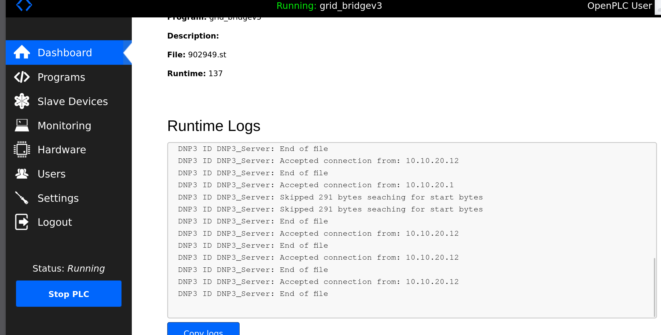 The outstation running
 grid_bridgev3, accepting DNP3 connections from the master at 10.10.20.12. -
Write the bridge program. This is the part the tutorials skip. OpenPLC keeps two separate register regions, and they do not overlap: addresses at
%IW100+/%QX100+are reserved for slave devices (the Modbus side), while the DNP3 outstation publishes from%IW0../%QX0... The DNP3 server literally cannot see the Modbus range. So the scan has to copy measurements up and commands down:1 2
ot-grid --Modbus--> %IW100+ --copy--> %IW0.. --DNP3--> master master --DNP3 CROB--> %QX0.. --copy--> %QX100+ --Modbus--> ot-grid
In Structured Text that’s two blocks of assignments and a heartbeat counter:
1
2
3
4
5
6
(* measurements up *)
ai_line09 := mb_line09;
(* commands down *)
mb_bk12   := bo_line12;

heartbeat := heartbeat + 1;
-
Poll from the master and confirm the values track the live simulation as the loop runs.
The bug that opened every breaker
The first version of that program worked perfectly and immediately tripped my entire substation.
I started the PLC, and the grid simulator’s log went from a healthy grid to this, on every cycle, forever:
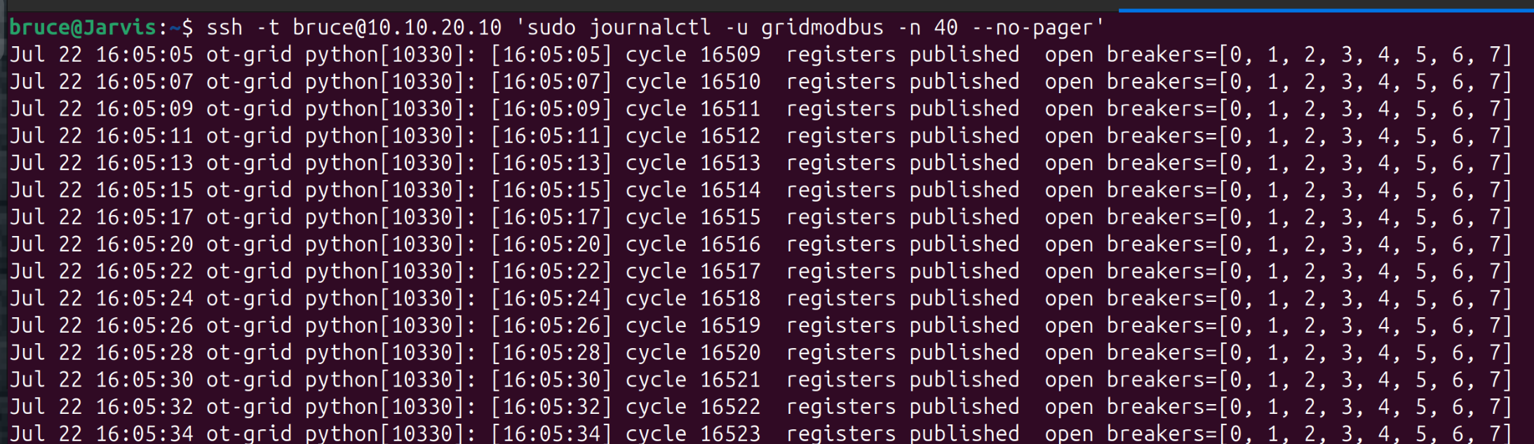 Every mapped breaker open — not because anyone sent a command, but because the PLC started.
Nothing sent a trip command. The cause is in OpenPLC’s own startup log, two lines that are easy to read past:
1
2
Persistent Storage is empty
Issued stop_pstorage() command
There’s no retained state, so on startup the output buffers come up as whatever the program
declares them as, and a BOOL you don’t initialize defaults to FALSE. My coil mapping treats
TRUE as closed, so the very first scan wrote sixteen zeros down to the grid, and ot-grid did
exactly what it was told and opened everything.
The fix is one keyword, repeated:
1
2
bo_line12 AT %QX1.4 : BOOL := TRUE;    (* from DNP3 binary output 12 (CROB) *)
mb_bk12   AT %QX101.4 : BOOL := TRUE;  (* to Modbus master: line 12 coil *)
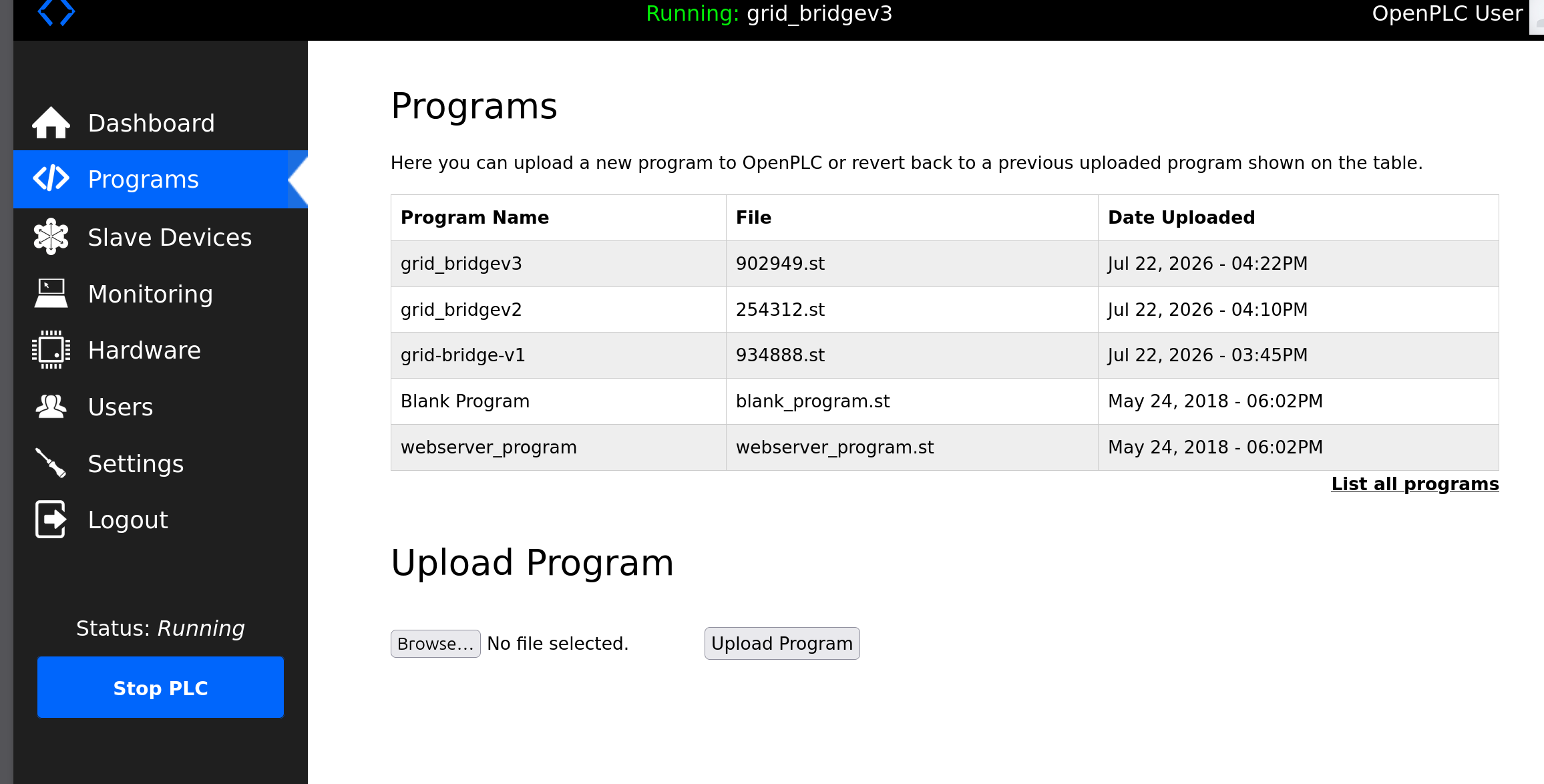 Three uploads in forty minutes. v1 is the one that tripped the grid.
I’m keeping this failure in the post because it isn’t just a lab quirk. It’s a real category of industrial incident, and it has a name: fail-safe versus fail-secure. Every output in a control system has a defined de-energized state, and somebody has to decide what it should be. Should a breaker fail open or fail closed? For a protective relay, fail-open is the safe answer: if the equipment isn’t sure, isolate the fault. For a bulk-power tie line carrying load to a city, opening on a controller reboot is itself the incident.
My PLC did have a defined startup behavior. Nobody had actually chosen it, though; the compiler chose it by zeroing memory. That’s the lesson for me: the defaults you never look at end up being your control philosophy, and the grid finds out before you do.
This is also why CIP-010 cares so much about configuration baselines and why a change to a single
.stfile is a change worth tracking. Post 6 builds that baseline in code.
Example: a legitimate breaker operation
With v3 running, here’s the intended path. An operator opens a breaker on purpose: the master sends a CROB, the outstation writes it into the coil, and the next pandapower solve redistributes the flows.
First, just polling — the control room’s normal view:
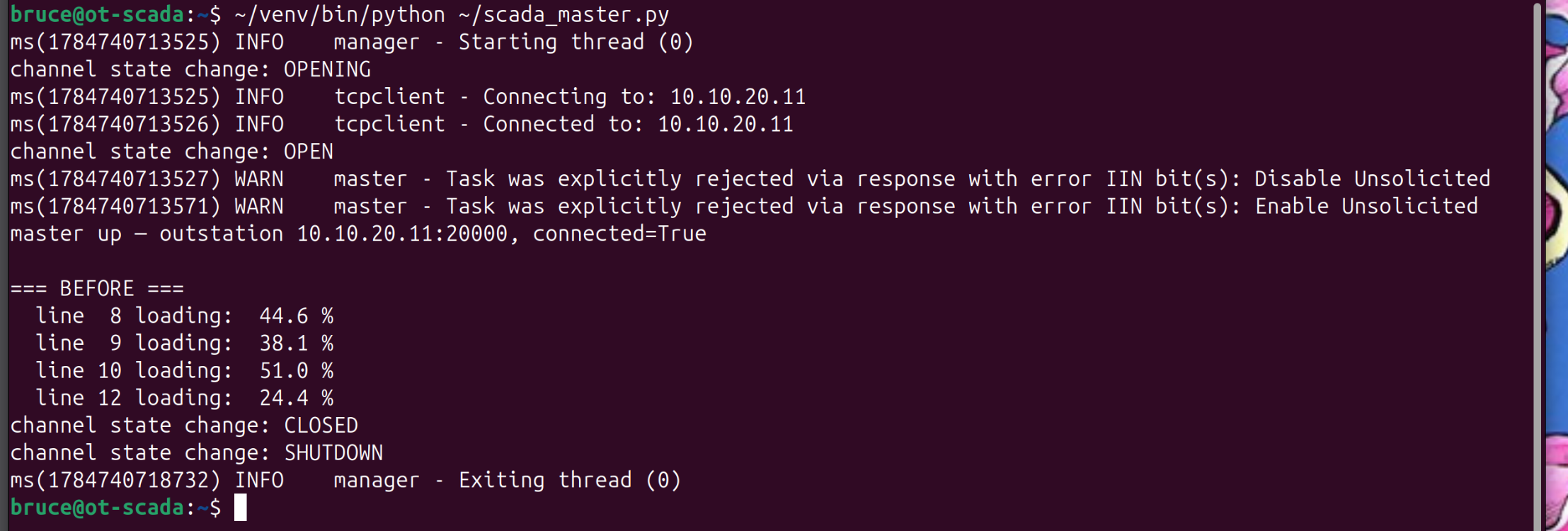 Line loadings arriving over DNP3 from a different VM. Line 9 reads 38.1% — the same value post 2
solved in pandapower.
Line loadings arriving over DNP3 from a different VM. Line 9 reads 38.1% — the same value post 2
solved in pandapower.
That number is worth a second look. In post 2, line 9 sat at 38.06% and the physics lived entirely inside one Python process. Here it reads 38.1%, after travelling Modbus → PLC scan → DNP3 → master across three machines. The grid didn’t change, only the path the number took did.
The missing hundredth is down to the plumbing too. Modbus and DNP3 registers are 16-bit integers, not floats, so the bridge carries loading as percent × 10 and the master divides it back out. One decimal place is all the protocol will give me. That isn’t a shortcut I took for the lab, it’s just how scaled integer point maps work in the real world, and it’s why comparing a SCADA reading against a simulation means agreeing on the scaling factor first.
Two warnings you’ll see and can ignore.
Task was explicitly rejected via response with error IIN bit(s): Disable Unsolicited/Enable Unsolicited. OpenPLC’s outstation doesn’t implement unsolicited reporting, so it rejects the master’s setup requests and polling proceeds normally. Real outstations are partial implementations too — the standard is large and vendors pick from it.
Now the command:
1
$ ~/venv/bin/python ~/scada_master.py --open 12
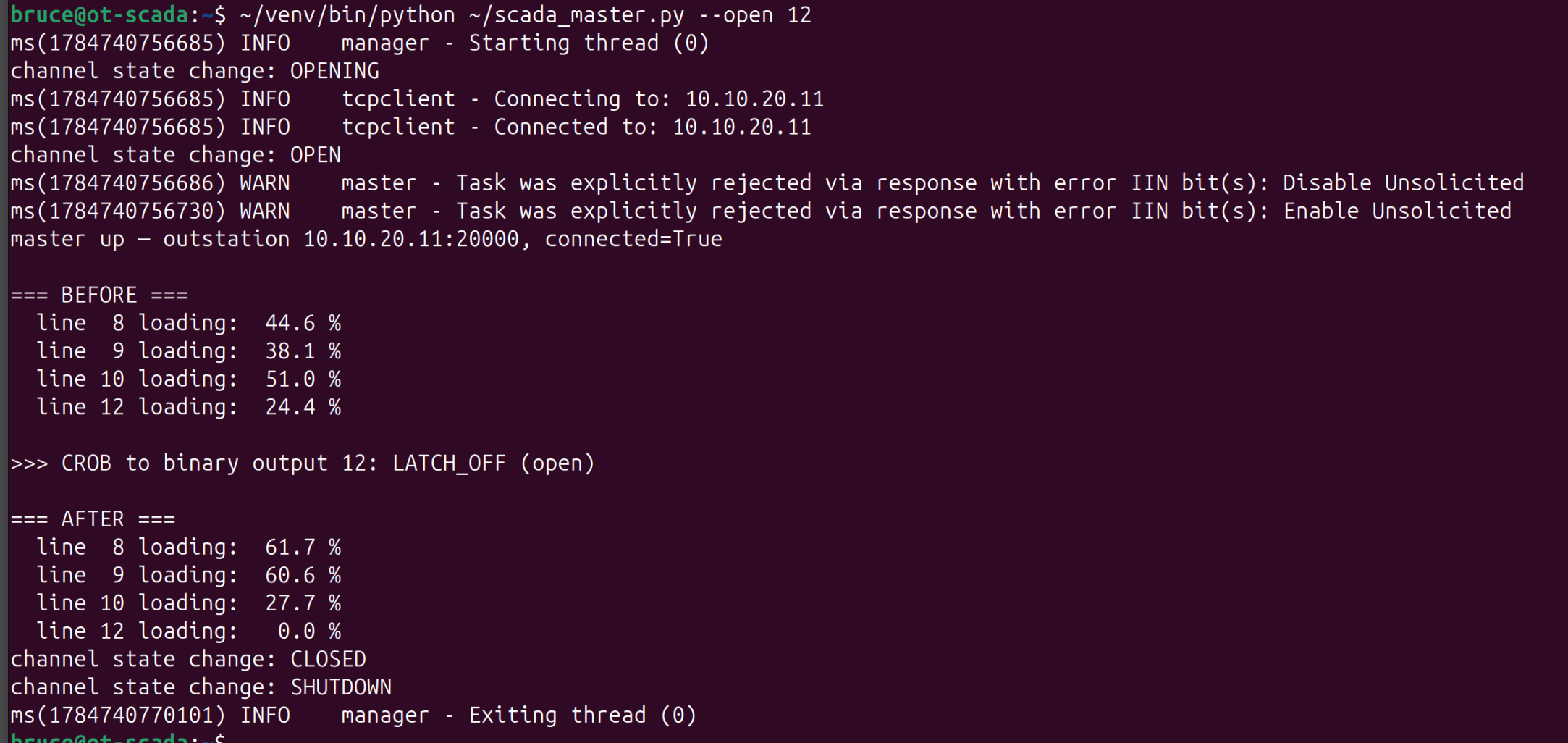 The closed control loop: command down, breaker opens, new analogs back up.
| Line | Before | After | Change |
|---|---|---|---|
| 8 | 44.6 % | 61.7 % | +17.1 |
| 9 | 38.1 % | 60.6 % | +22.5 |
| 10 | 51.0 % | 27.7 % | −23.3 |
| 12 | 24.4 % | 0.0 % | opened |
Line 12 goes to zero, and lines 8 and 9 absorb what it was carrying — line 9 landing on 60.6%, the exact figure post 2 predicted from the model alone.
And line 10 drops 23 points, for the reason post 2 worked through: it was a transit path to bus 7, and with the breaker open it falls back to serving only bus 6’s local load. The point worth carrying into post 5 is that the largest change in the system was a circuit getting quieter — detection that only looks for numbers going up will miss it.
The same command, unauthorized — and why you can’t tell
Now the attacker’s version. There is nothing in the protocol that separates it from the operator’s command. It’s not that it’s hard to tell them apart; there’s genuinely nothing there to tell them apart with.
Here’s the CROB from the capture above, decoded:
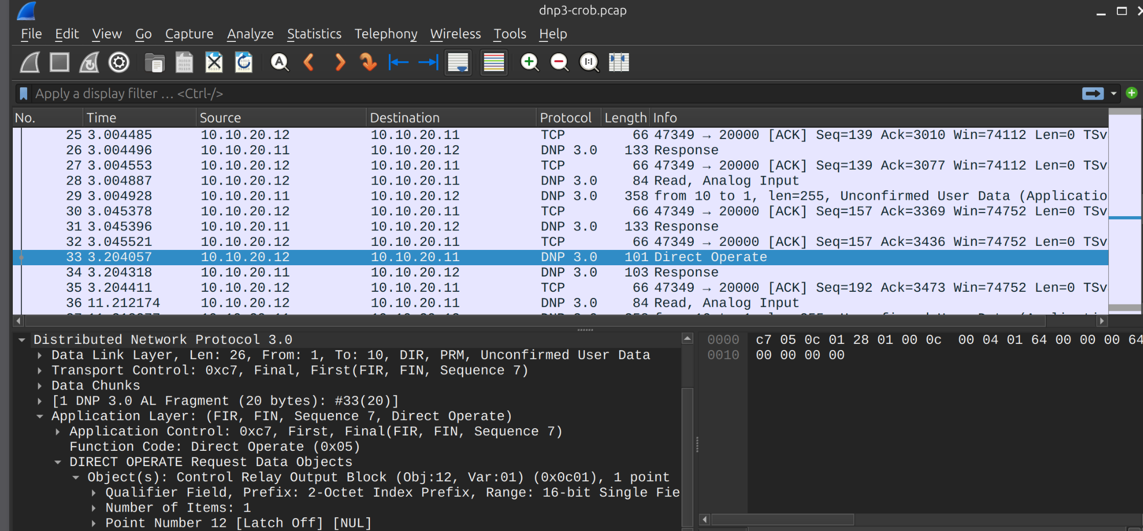 Frame 33: Direct Operate, Control Relay Output Block, Point Number 12, Latch Off.
Twenty bytes of application layer, and every one of them accounted for:
| Bytes | Meaning |
|---|---|
c7 |
Application control — first, final, sequence 7 |
05 |
Function code 5 — Direct Operate |
0c 01 |
Object group 12, variation 1 — Control Relay Output Block |
28 |
Qualifier — 1-byte count, 2-byte index |
01 00 |
Count: 1 point |
0c 00 |
Index: 12 — the breaker |
04 |
Control code 0x04 — LATCH_OFF |
01 |
Count: 1 |
64 00 00 00 |
On-time: 100 ms |
64 00 00 00 |
Off-time: 100 ms |
00 |
Status |
Look at the table again and notice what’s missing. There’s no credential, no signature, no session
token, no nonce, no certificate, no user field. The link layer carries From: 1, To: 10, two small
integers that the sender picks and nobody checks. An attacker who reaches port 20000 sends these
same twenty bytes and gets the same result, because they literally are the same twenty bytes.
That’s the whole thing this series is built around, and it’s why the rest of it focuses on everything around the protocol instead of the protocol itself.
An unauthorized CROB opening a breaker is the 2015 Ukraine attack, reduced to its essence. I’m not exploiting a bug — I’m using the protocol exactly as designed, from the wrong place. Hold that thought; post 4 (the ESP) is about making “the wrong place” impossible to reach, and post 5 is about catching it when someone reaches anyway.
An unexpected door, found by accident
One more thing from the outstation’s startup log:
1
2
Issued start_enip() command to start on port: 44818
Server: Listening on port 44818
I never asked for EtherNet/IP. It’s on by default, listening inside the ESP, on a device whose only job is to speak DNP3 to one master. That’s a textbook CIP-007 R1 finding (only enable the ports and services the device actually needs), and I found it by reading a startup log, not by scanning for it.
That’s honestly how a lot of these findings turn up: not from a tool, but from noticing a line you didn’t expect in output you were reading for another reason. Post 6 automates that noticing.
Optional: IEC 61850 for substation realism
Once the DNP3 loop is rock-solid, IEC 61850 adds modern substation protocols — MMS (polling, TCP 102) and GOOSE (fast, non-routable Layer-2 protection messaging). Great fodder for the INSM work later. Sequencing matters: layer this in only after DNP3 is stable end-to-end.
Verifying it worked
The protocol layer is real if all three of these are true:
- The master’s analog inputs track the pandapower loop — line 9 reads the same value the solver produced.
- A CROB changes a breaker and the resulting flows — and closing it again returns the
system to baseline, which it does:
44.6 / 38.1 / 51.0 / 24.4, exactly where it started. - The traffic is visible on the wire between two VMs, not looping back on localhost. The
capture settles this: the Ethernet header reads
52:54:00:10:20:0c → 52:54:00:10:20:0b, the two OT-zone NICs, and the IP layer10.10.20.12 → 10.10.20.11. Nothing here is a function call dressed up as a protocol.
The capture is 61 packets, 45 of them DNP3, and it holds the whole session: Disable Unsolicited,
Enable Unsolicited, the periodic Read polls, the Direct Operate, and the outstation’s
response.
You don’t have to take my word for any of it. Here is the capture:
📦 dnp3-crob.pcap — 12 KB, 61 packets. Open it in Wireshark and jump to frame 33, or read the bytes yourself:
Check my arithmetic on those twenty bytes. More usefully, go looking for the field that says who sent the command, and satisfy yourself that it isn’t there.
Default port reference
| Protocol | Port | Notes |
|---|---|---|
| DNP3 (TCP) | 20000 | Master ↔ outstation |
| Modbus TCP | 502 | OpenPLC ↔ grid simulator in this lab |
| EtherNet/IP | 44818 | Enabled by default — disable if unused |
| IEC 61850 MMS | 102 | Polling / reporting |
| IEC 61850 GOOSE | L2 multicast | Fast protection msgs; not routable |
Wrap-up
The grid now speaks the same protocol real utilities use, and I can open or close a breaker over DNP3, legitimately or not. Two things came out of building it that I didn’t plan for: a PLC that opened every breaker on startup because nobody had decided what “de-energized” should mean, and a protocol whose command frame has room for a hundred-millisecond timing parameter but not a single bit for identity.
The uncomfortable takeaway is that the malicious command and the legitimate one are byte-for-byte identical. There’s no payload to write a signature for and no exploit to patch. That’s why OT defense looks so different from IT defense, and it’s the assumption the next three posts build on.
Everything so far has been about building something worth protecting. The next post switches to defense: drawing the Electronic Security Perimeter around this OT zone, standing up the EAP, and forcing all remote access through a jump host under CIP-005.